Moblie

Monday, October 5, 2015

Cisco UCS with Nexus VPC

Note:
1. Cisco UCS Mini 5108 with Fabric interconnect 6324
2. Cisco  Nexus 3000k pair.
3. Cross connection topology .
4. Only VPC configuration display
5. Only UCS link configuration shown.

------------------------------------------------------------------------------


------------------------------------Nexus Switch-1----------------------------------------------------------
CORW-NX-SW1#  sh run


feature lacp
feature vpc
feature lldp
feature vtp


interface mgmt0
  ip address 10.10.10.1/24

vrf context management
  ip route 10.10.10.0/24 10.10.10.2

vpc domain 1
  peer-keepalive destination 10.10.10.2
  peer-gateway


!
interface port-channel50
  switchport mode trunk
  spanning-tree port type network
  speed 10000
  vpc peer-link

interface port-channel101
  description ** VPC link to UCS-F1 **
  switchport mode trunk
  speed 10000
  vpc 101

interface port-channel102
  description ** VPC link to UCS-F2 **
  switchport mode trunk
  speed 10000
  vpc 102

interface Ethernet1/1
  description ** UCS-F1-1 **
  switchport mode trunk
  channel-group 101 mode active


interface Ethernet1/2
  description ** UCS-F2-1 **
  switchport mode trunk
  channel-group 102 mode active


interface Ethernet1/46
  description ** NEXUS-SW2 VPC link **
  switchport mode trunk
  channel-group 50 mode active


interface Ethernet1/47
  description ** NEXUS-SW2 VPC link **
  switchport mode trunk
  channel-group 50 mode active


-----------------------------Nexus Switch-2 -------------------------------------
CORE-NX-SW2# sh run

 feature lacp
feature vpc
feature lldp
feature vtp


vrf context management
  ip route 10.10.10.0/24 10.10.10.1


vpc domain 1
  peer-keepalive destination 10.10.10.1


interface mgmt0
  ip address 10.10.10.2/24

!
interface port-channel50
  switchport mode trunk
  spanning-tree port type network
  speed 10000
  vpc peer-link

interface port-channel101
  description ** VPC link to UCS-F1 **
  switchport mode trunk
  speed 10000
  vpc 101

interface port-channel102
  description ** VPC link to UCS-F2 **
  switchport mode trunk
  speed 10000
  vpc 102

interface Ethernet1/1
  description ** UCS-F2-P1 **
  switchport mode trunk
  channel-group 101 mode active


interface Ethernet1/46
  description ** NEXUS-SW1 VPC link **
  switchport mode trunk
  channel-group 50 mode active


interface Ethernet1/47
  description ** NEXUS-SW1 VPC link **
  switchport mode trunk
  channel-group 50 mode active


----------------------------------UCS Configuration-------------------------------------------

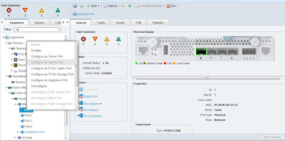
Configure Ports on UCS Steps

1. Select the ports individually and right click on the port.
2. Select Configure as Uplink Port.


Fabric -1
 . Port-1
 . Port-2

Fabric -2
 . Port-1
 . Port-2


---------------------------------------------------------------------------------- ----------

Configure Port Channel on UCS

1. Go to LAN Tab
2. Go to Fabric -A
3. Right Click on Port Channels 
4. Click on Create Port Channel 


5. Select and add ports.


 6. Finish.
7. Now select Fabric-B and apply steps (2 to 6)


Your all connect Ports should look green.

-----------------------------------------------------------------------------------------


Troubleshoot commands.

Show vpc


-CORW-NX-SW1# sh vpc consistency-parameters vpc 102


Testing on both Nexus switch and the result should be Up and success.


vPC status
----------------------------------------------------------------------------
id     Port        Status Consistency Reason                     Active vlans
------ ----------- ------ ----------- -------------------------- -----------
101    Po101       up     success     success                    1,10-14
102    Po102       up     success     success                    1,10-14


Friday, September 18, 2015

Remote Client VPN on Cisco 800 Router

Cisco Router 891 , Cisco Remote VPN Client


!
interface GigabitEthernet0
 description ** WAN Internet Link ***
 ip address 38.93.235.182 255.255.255.128
 ip nat outside
 ip virtual-reassembly in
 duplex auto
 speed auto
 crypto map EXT_MAP
!

interface Vlan1
 ip address 192.168.110.10 255.255.255.0
 ip nat inside
 ip virtual-reassembly in


ip local pool VPN_CLIENT_POOL 192.168.200.20 192.168.200.100
ip forward-protocol nd
!
!
ip http server
no ip http secure-server
ip nat inside source route-map NAT_INT interface GigabitEthernet0 overload
ip route 0.0.0.0 0.0.0.0 38.93.235.254
!
a
access-list 101 deny   ip 192.168.110.0 0.0.0.255 192.168.200.0 0.0.0.255
access-list 101 permit ip 192.168.110.0 0.0.0.255 any
access-list 101 permit ip 192.168.111.0 0.0.0.255 any
access-list 101 permit ip 192.168.112.0 0.0.0.255 any
access-list 101 permit ip 192.168.113.0 0.0.0.255 any
access-list 101 deny   ip any any
access-list 110 permit ip 192.168.110.0 0.0.0.255 192.168.200.0 0.0.0.255
!
!
!
!
route-map NAT_INT permit 1
 match ip address 101
!
!

aaa new-model
!
!
aaa authentication login ciscocp_vpn_xauth_ml_1 local
aaa authorization exec default local
aaa authorization network ciscocp_vpn_group_ml_1 local
!
!
!
!
username admin privilege 15 password 0 admin2015
username vpnuser secret 5 XXXXXXXX

!
crypto isakmp policy 10
 encr 3des
 authentication pre-share
 group 2
 lifetime 3600
!
crypto isakmp client configuration group vpnuser
 key admin@2015
 dns 8.8.8.8
 domain turbo.com
 pool VPN_CLIENT_POOL
 acl 110
!

!
crypto ipsec transform-set TRANS_3DES_SHA esp-3des esp-sha-hmac
!
crypto dynamic-map EXT_DYNAMIC_MAP 10
 set transform-set TRANS_3DES_SHA
!
!
crypto map EXT_MAP client authentication list ciscocp_vpn_xauth_ml_1
crypto map EXT_MAP isakmp authorization list ciscocp_vpn_group_ml_1
crypto map EXT_MAP client configuration address respond
crypto map EXT_MAP 10 ipsec-isakmp dynamic EXT_DYNAMIC_MAP
!
!
!


Thursday, August 20, 2015

Cisco CUE 8.6 General Delivery Mailbox (GDM)


Cisco CUE 8.6 General   Delivery Mailbox (GDM)

Note:
1. CME 10.5 and CUE 8.6 IOS version
2.  User are configure in CUE and CME.
3. Only add member and owner in GDM
4. Using one PSTN direct line number. E.164 number  4083994000
5. My 202 and 203 extension already configure in CME and CUE.
6. 202 and 203 are the member and owner in GDM.
7. CME and CUE basic config already there. showing only step to creating GDM
8. Extension 301 is my hunt group.
9. for basic config check this link
 http://cisconetlabs.blogspot.in/2015/08/cme-call-forward-to-mobile-phone.html


--------------------------------Steps -Picture ---------------------------------------
1. Login to yours CUE via web access

2. Create Group.
3. After create the Voicemail group shown in the Voice mail --> mailboxes

4. Go to the Group and add your Primary extension number and E.164 number


 5. Add user in this group. member and owner

6. Check mailbox setting
7. Configure mail box setting . some are default.
8. check greeting


9. Check caller input
10. Refresh MWI message waiting indication.
 11. Check the VM configuration


Wednesday, August 19, 2015

CME Call forward to Mobile phone


CME Call forwarding to Mobile phone


1.Using Voice Hunt group 301 is use for GDM
2. 202 and 203 are the extension number
3. If user enable call forward button on IP phone on given mobile number
4. 9 is use for prefix number
5. Using SIP IP Phone
6. Don't change the timer. timer play big role in call forward
7. Using Direct PSTN lines .. No ISDN.
----------------------------------------------------------------------------------------

!
voice service voip
 allow-connections h323 to h323
 allow-connections h323 to sip
 allow-connections sip to h323
 allow-connections sip to sip
 no supplementary-service sip moved-temporarily
 no supplementary-service sip refer
 no supplementary-service sip handle-replaces
 supplementary-service media-renegotiate
 redirect ip2ip
 fax protocol t38 version 0 ls-redundancy 0 hs-redundancy 0 fallback none
 sip
  bind control source-interface    << Interface >>
  bind media source-interface      << Interface name fa0/1  >>>
  registrar server
  no silent-discard untrusted

!

voice register global
 mode  cme
 source-address <> ; port 5060
 max-dn 10
 max-pool 10
 load 6921 cmterm-69xx-sip.9-4-1-3.cop.sgn
 load 7841 cmterm-78xx.10-3-1-12.k3.cop.sgn
 timezone 12
 hold-alert
 voicemail 299
 tftp-path flash:
 create profile 

!

voice register dn  1
 number 202
call-forward b2bua all 4092227890     // Mobile number for forward phone
 call-forward b2bua busy 299 
 call-forward b2bua noan 299 timeout 15
 name JAMES
 label JAMES
 mwi
!

!
voice register dn  2
 number 203
 call-forward b2bua busy 299 
 call-forward b2bua noan 299 timeout 20
 name BOB
 label BOB
 mwi


!
voice register pool  1
 busy-trigger-per-button 1
 id mac xxxx.xxxx.xxxx
 type 7841
 number 1 dn 1
 dtmf-relay rtp-nte
 username james password 123456
!
voice register pool  2
 busy-trigger-per-button 1
 id mac xxxx.xxxx.xxxx
 type 7841
 number 1 dn 2
 dtmf-relay rtp-nte
 username bob password 123456

!
voice hunt-group 1 parallel
 final 202
 list 203,202
 timeout 10
 pilot 301
!
voice translation-rule 1
 rule 1 /^9/ //
!
!
voice translation-profile OutgoingProfile_1
 translate called 1

trunk group XYZ
!
voice-port 0/0/0
 trunk-group XYZ
 connection plar opx 301
 description 2034516666
 caller-id enable
!
voice-port 0/0/1
 trunk-group XYZ
 connection plar opx 301
 description 2034312345
 caller-id enable
!
voice-port 0/0/2
 trunk-group XYZ
 connection plar opx 301
 description 2034445555
 caller-id enable

!
dial-peer voice 1 pots
 trunkgroup XYZ
 description Local
 translation-profile outgoing OutgoingProfile_1
 destination-pattern 9[2-9].........
 forward-digits all
!
dial-peer voice 2 pots
 trunkgroup XYZ
 description National Long Distance
 translation-profile outgoing OutgoingProfile_1
 destination-pattern 91[2-9]..[2-9]......
 forward-digits all
!
dial-peer voice 3 pots
 trunkgroup XYZ
 description International
 translation-profile outgoing OutgoingProfile_1
 destination-pattern 9011T
 forward-digits all

!
dial-peer voice 4 voip
 destination-pattern 299
 session protocol sipv2
 session target ipv4:10.x.x.x
 dtmf-relay sip-notify
 codec g711ulaw
 no vad

Sunday, August 9, 2015

OTV Feature


OTV Features

1. Multi Vlan allowed on OTV
2. SITE Vlan work with two peer links e:g between two edge router.
3. OTV with Multicast is default Behavior
4. OTV use ISIS protocol with L2 Mac address advertise
5. MAC in IP routing (MPSL, GRE)
6. OTV can use any type of link , (DS3, SONET, P2P) need only IP v4 reachabilty
7. CE Edge device can any type of routing (e:g BGP, OSP, Eigrp)
8. Site identifier work as loop prevention system on OTV

Problem in OTV and feature  Limitation in OTV

1. Cannot run OTV inside the same VDC where you have L3 Vlans and (HSRP, GLBP)
2. For OTV you need to use Different VDC or differ Nexus7k switch, if we have L3 Vlan with HSRP or GLBP.
3. Between A site to B site the multicast need enable on PE routers. ISP will provide the feature with L2 MPLS links.
4. License should need to buy for OTV ( But for grace days we can use OTV as demo)


Cisco Hardware support OTV Feature


    1. Nexus 7000/7700
        Yes.
        M1/M2 series cards for the join interface
        The forthcoming F3 series cards will also support OTV encap/decap and can be used as the join interface

   2.  ASR 1000
        Yes. The Quantum Flow Processor in the ASR allows it to support OTV. Requires IOS-XE 3.5.0S and higher. 

    3. Nexus 5500
        No, and never will. Switching ASICs do not support OTV.

   4.  Nexus 6000
        No, and never will. Switching ASICs do not support OTV.

Note: These might not be the latest figures.


                                                    OTV Topology Diagram

Benefits of OVT over the other DCI


DCI (Data Centre Interconnect) Links v/s  OTV


Friday, August 7, 2015

CME Not support IP Phone Personal address book

CME version 10.5 is not support Personal address book.

Note: 
1. This post only check and Test on SIP IP phone 7841.
2. Cisco Router 2921   IOSv15.  CME 10.5
3. User can't do add Personal phone entry in IP Phone address book.
4. Only speed dial option is available but it can done by Cisco Administrator. Those have the router and CME access.
5. Only three option show on IP phone.(7841 IP Phone)
             (1) Local Directory
             (2) Local Speed dial
             (3) Personal Speed Dial 

6.  Personal address book is supported on CME version 8.0 and above. But this Feature is different name Personal Speed dial
7. It is not possible in CME for end user to populate his own list in Fast Dial.
8. After doing the below configuration, then the end user can see the numbers populated on his phone .        9. However, end user himself cannot modify that, only an administrator who has access to CME can do that. 
10. 


Checkout below link:

This feature is named as personal speed dial


-------------------SIP Phone add  contact-------------------
voice register dn  1
 number 201
 call-forward b2bua busy 299 
 call-forward b2bua noan 299 timeout 20
 name  user-1
 label  user-1


voice register pool  1
 busy-trigger-per-button 1

 fastdial 1 9408xxxxxx name ABC Companay      // you can add 100 contacts
  id mac 204C.9EB3.D786
 type 7841
 number 1 dn 1
 dtmf-relay rtp-nte
 username user-1 password 123456
 speed-dial 1 202 label "User-2"
 speed-dial 2 210 label "User-10"
 speed-dial 3 201 label "User-1"

 speed-dial 90 9409xxxxxxx label "XYZ compnay"     // You can add more than 100 contact
!
 
-----------------------------------------------------------------------

Sample configuration:
=====================
ephone  2
device-security-mode none
mac-address 0016.C82D.5407
fastdial 1 911 name EMER -> Fastdial command under ephone
type 7961
button  1:2 2:3 3:4 4:5
button  5:6

telephony-service
service dnis dir-lookup ->To enable local directory

ip http server
ip http path flash:

------------------------------------------For SIP IP Phone ---------------------------------


voice register dn  1
 number 201
 call-forward b2bua busy 299 
 call-forward b2bua noan 299 timeout 20
 name  user-1
 label  user-1


voice register pool  1
 busy-trigger-per-button 1
 id mac 204C.9EB3.D786
 type 7841
 number 1 dn 1
 dtmf-relay rtp-nte
 username user-1 password 123456
 speed-dial 1 202 label "User-2"
 speed-dial 2 210 label "User-10"
 speed-dial 3 201 label "User-1"
!

________________________________________________________________________________-


Cisco Online labs


Online LAB's Link

http://labswitch.blogspot.in/
http://www.sharontools.com/online-lab

CME Configuration with SIP Phone 7841

CME v2 10.5 and  2921 Router  CUE 8.6

Note:
1. Configuration for Cisco SIP IP Phones
2. Configuration of  Voice dial Peer
3. Configuration Translation rule.
4. Basic Configuration CUE
5. DHCP and IP configuration
  _____________________________________

--------First Step ----------------


voice service voip
 allow-connections h323 to h323
 allow-connections h323 to sip
 allow-connections sip to h323
 allow-connections sip to sip
 no supplementary-service sip moved-temporarily
 no supplementary-service sip refer
 no supplementary-service sip handle-replaces
 fax protocol t38 version 0 ls-redundancy 0 hs-redundancy 0 fallback none
 sip
  bind control source-interface Vlan100
  bind media source-interface Vlan100
  registrar server
  no silent-discard untrusted

---------Second Step -------

voice register global
 mode  cme
 source-address 10.1.110.1 port 5060
 max-dn 10
 max-pool 10
 load 6921 cmterm-69xx-sip.9-4-1-3.cop.sgn
 load 7841 cmterm-78xx.10-3-1-12.k3.cop.sgn
 timezone 12
 hold-alert
 voicemail 299
 tftp-path flash:
 create profile

------Third Step-----------

voice register dn  1
 number 202
 call-forward b2bua busy 299 
 call-forward b2bua noan 299 timeout 18
 name Sebastian USERNAME-1
 label Sebastian USERNAME-1
 mwi
!
voice register dn  2
 number 203
 call-forward b2bua noan 299 timeout 18
 name Adriana USERNAME-2
 label Adriana USERNAME-2
 mwi

------Fourth Step ----------

!
voice register pool 1
 busy-trigger-per-button 1
 id mac 204C.9EB3.DA2D
 type 7841
 number 1 dn1
 dtmf-relay rtp-nte
 username USERNAME-1 password 123456
!
voice register pool 2
 busy-trigger-per-button 1
 id mac 204C.9EB3.D676
 type 7841
 number 1 dn 2
 dtmf-relay rtp-nte
 username USERNAME-2 password 123456

-------Fifth Step----Important ----

voice register global
 create profile
________________________________________

-------VOICE Port Configuration ----------

voice hunt-group 1 parallel
 final 299            // This is the Voicemail number
 list 202,203          // user will Recice the call
 timeout 30           // Call transfer to voicemail after time
 pilot 301
!

----------PSTN direct Number config------

I have only direct number or plane number .. NO ISDN , NO DID
----
!
trunk group DIRECT

!
voice-port 0/0/0
 trunk-group DIRECT
 connection plar opx 301
 description 2052611234  //MAIN Line 1
 caller-id enable
!
voice-port 0/0/1
 trunk-group DIRECT
 connection plar opx 301
 description 2052614567  //Line 2
 caller-id enable
!
voice-port 0/0/2
 trunk-group DIRECT
 connection plar opx 301
 description 2052616789  //Line 2
 caller-id enable


------Outgoing call Translation Rule--------


voice translation-rule 1
 rule 1 /^9/ //
!
!
voice translation-profile OutgoingProfile_1
 translate called 1

---------Voice Dial Pattren -----
dial-peer voice 1 pots
 trunkgroup DIRECT
 description Local
 translation-profile outgoing OutgoingProfile_1
 destination-pattern 9[2-9].........
 forward-digits all
!
dial-peer voice 2 pots
 trunkgroup DIRECT
 description National Long Distance
 translation-profile outgoing OutgoingProfile_1
 destination-pattern 91[2-9]..[2-9]......
 forward-digits all
!
dial-peer voice 3 pots
 trunkgroup DIRECT
 description International
 translation-profile outgoing OutgoingProfile_1
 destination-pattern 9011T
 forward-digits all
!

-----Voicemail Dial-----
dial-peer voice 4 voip
 destination-pattern 299
 session protocol sipv2
 session target ipv4:10.1.110.2
 dtmf-relay sip-notify
 codec g711ulaw
 no vad
!
dial-peer voice 5 voip
 destination-pattern 300
 session protocol sipv2
 session target ipv4:10.1.110.2
 dtmf-relay sip-notify
 codec g711ulaw
 no vad


--------------CUE IP Integration-------------
sip-ua
 mwi-server ipv4:10.1.110.2 expires 3600 port 5060 transport udp


interface ISM0/0
 description CUE
 ip unnumbered Vlan100
 ip nat inside
 ip virtual-reassembly in
 service-module ip address 10.1.110.2 255.255.255.0
 !Application: CUE Running on ISM
 service-module ip default-gateway 10.1.110.1

interface Vlan100
 ip address 10.1.110.1 255.255.255.0
 ip nat inside
 ip virtual-reassembly in

ip route 10.1.110.2 255.255.255.255 ISM0/0
!

-------DHCP For Voice ---------

ip dhcp pool Voice
 import all
 network 10.1.110.0 255.255.255.0
 option 150 ip 10.1.110.1
 default-router 10.1.110.1
!

-----------------Done-----------


Saturday, July 11, 2015

Sunday, June 14, 2015

ISR Router WAN Performance & Throughput

WAN Router Throughput 

• 1941/2901 - up to 25Mbps
• 2911 - up to 35Mbps
• 2921 - up to 50Mbps
• 2951 - up to 75Mbps
• 3925 - up to 100Mbps
• 3945 – up to 150Mbps

Friday, May 15, 2015

VSS Cisco Switch 4500 Configuration

VSS Configuration Cisco 4500 Switch

1.  Cisco Catalyst 4500-E Series Switches with Cisco Catalyst Supervisor Engine 7-E.
2. Create VSL Link between two switches.VSS members are connected by virtual switch
   links (VSLs) using standard Gigabit or 10 Gigabit Ethernet
3. Use Cisco IOS-XE Software 3.0 and above


Step 1.:   Assigning Virtual Switch Domain and Switch Numbers
-------------------STEP-1------------------------------------
SW1 Configuration
*****************

SW1(config)#switch virtual domain 10
SW1(config-vs-domain)#switch 1

===================================

SW2  Configuration
******************

SW2(config)#switch virtual domain 10
SW2(config-vs-domain)#switch 2
_____________________________________________________________

Step 2 :   Configuring VSL Port Channel
-----------------STEP-2----------------------
SW1 Configuration
*****************

SW1(config)#int port-channel 6
SW1(config-if)#switchport
SW1(config-if)#switch virtual link 1
SW1(config-if)#no shut
=====================================
SW2  Configuration
******************

SW2(config)#int port-channel 10
SW2(config-if)#switchport
SW2(config-if)#switch virtual link 2
SW2(config-if)#no shut

______________________________________________________


Step 3 :   Configuring VSL Port Channel
----------------STEP-3---------------------------------
SW1 Configuration
*****************

SW1(config)#int range gig1/1 - 2
SW1(config-if-range)#switchport mode trunk
SW1(config-if-range)#channel-group 6 mode on

=============================================
SW2  Configuration
***************

SW2(config)#int range gig4/47 - 48
SW2(config-if-range)#switchport mode trunk
SW2(config-if-range)#channel-group 10 mode on

_______________________________________________________

Step 4 :   Converting the Switch to Virtual Switch Mode
----------------STEP-4-------------------------
SW1 Configuration
*****************
SW1#switch convert mode virtual

============================================
SW2  Configuration
***************
SW2#switch convert mode virtual


++++++++++++++++++END++++++++++++++++++++++


Wednesday, February 25, 2015