Note:
1. Cisco UCS Mini 5108 with Fabric interconnect 6324
2. Cisco Nexus 3000k pair.
3. Cross connection topology .
4. Only VPC configuration display
5. Only UCS link configuration shown.
------------------------------------------------------------------------------

------------------------------------Nexus Switch-1----------------------------------------------------------
CORW-NX-SW1# sh run
feature lacp
feature vpc
feature lldp
feature vtp
interface mgmt0
ip address 10.10.10.1/24
vrf context management
ip route 10.10.10.0/24 10.10.10.2
vpc domain 1
peer-keepalive destination 10.10.10.2
peer-gateway
!
interface port-channel50
switchport mode trunk
spanning-tree port type network
speed 10000
vpc peer-link
interface port-channel101
description ** VPC link to UCS-F1 **
switchport mode trunk
speed 10000
vpc 101
interface port-channel102
description ** VPC link to UCS-F2 **
switchport mode trunk
speed 10000
vpc 102
interface Ethernet1/1
description ** UCS-F1-1 **
switchport mode trunk
channel-group 101 mode active
interface Ethernet1/2
description ** UCS-F2-1 **
switchport mode trunk
channel-group 102 mode active
interface Ethernet1/46
description ** NEXUS-SW2 VPC link **
switchport mode trunk
channel-group 50 mode active
interface Ethernet1/47
description ** NEXUS-SW2 VPC link **
switchport mode trunk
channel-group 50 mode active
-----------------------------Nexus Switch-2 -------------------------------------
CORE-NX-SW2# sh run
feature lacp
feature vpc
feature lldp
feature vtp
vrf context management
ip route 10.10.10.0/24 10.10.10.1
vpc domain 1
peer-keepalive destination 10.10.10.1
interface mgmt0
ip address 10.10.10.2/24
!
interface port-channel50
switchport mode trunk
spanning-tree port type network
speed 10000
vpc peer-link
interface port-channel101
description ** VPC link to UCS-F1 **
switchport mode trunk
speed 10000
vpc 101
interface port-channel102
description ** VPC link to UCS-F2 **
switchport mode trunk
speed 10000
vpc 102
interface Ethernet1/1
description ** UCS-F2-P1 **
switchport mode trunk
channel-group 101 mode active
interface Ethernet1/46
description ** NEXUS-SW1 VPC link **
switchport mode trunk
channel-group 50 mode active
interface Ethernet1/47
description ** NEXUS-SW1 VPC link **
switchport mode trunk
channel-group 50 mode active
----------------------------------UCS Configuration-------------------------------------------
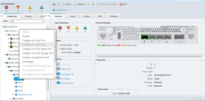
Configure Ports on UCS Steps
1. Select the ports individually and right click on the port.
2. Select Configure as Uplink Port.
Fabric -1
. Port-1
. Port-2
Fabric -2
. Port-1
. Port-2
---------------------------------------------------------------------------------- ----------
Configure Port Channel on UCS
1. Go to LAN Tab
2. Go to Fabric -A
3. Right Click on Port Channels
4. Click on Create Port Channel

5. Select and add ports.

6. Finish.
7. Now select Fabric-B and apply steps (2 to 6)
Your all connect Ports should look green.
-----------------------------------------------------------------------------------------
Troubleshoot commands.
Show vpc

-CORW-NX-SW1# sh vpc consistency-parameters vpc 102

Testing on both Nexus switch and the result should be Up and success.
vPC status
----------------------------------------------------------------------------
id Port Status Consistency Reason Active vlans
------ ----------- ------ ----------- -------------------------- -----------
101 Po101 up success success 1,10-14
102 Po102 up success success 1,10-14
1. Cisco UCS Mini 5108 with Fabric interconnect 6324
2. Cisco Nexus 3000k pair.
3. Cross connection topology .
4. Only VPC configuration display
5. Only UCS link configuration shown.
------------------------------------------------------------------------------

------------------------------------Nexus Switch-1----------------------------------------------------------
CORW-NX-SW1# sh run
feature lacp
feature vpc
feature lldp
feature vtp
interface mgmt0
ip address 10.10.10.1/24
vrf context management
ip route 10.10.10.0/24 10.10.10.2
vpc domain 1
peer-keepalive destination 10.10.10.2
peer-gateway
!
interface port-channel50
switchport mode trunk
spanning-tree port type network
speed 10000
vpc peer-link
interface port-channel101
description ** VPC link to UCS-F1 **
switchport mode trunk
speed 10000
vpc 101
interface port-channel102
description ** VPC link to UCS-F2 **
switchport mode trunk
speed 10000
vpc 102
interface Ethernet1/1
description ** UCS-F1-1 **
switchport mode trunk
channel-group 101 mode active
interface Ethernet1/2
description ** UCS-F2-1 **
switchport mode trunk
channel-group 102 mode active
interface Ethernet1/46
description ** NEXUS-SW2 VPC link **
switchport mode trunk
channel-group 50 mode active
interface Ethernet1/47
description ** NEXUS-SW2 VPC link **
switchport mode trunk
channel-group 50 mode active
-----------------------------Nexus Switch-2 -------------------------------------
CORE-NX-SW2# sh run
feature lacp
feature vpc
feature lldp
feature vtp
vrf context management
ip route 10.10.10.0/24 10.10.10.1
vpc domain 1
peer-keepalive destination 10.10.10.1
interface mgmt0
ip address 10.10.10.2/24
!
interface port-channel50
switchport mode trunk
spanning-tree port type network
speed 10000
vpc peer-link
interface port-channel101
description ** VPC link to UCS-F1 **
switchport mode trunk
speed 10000
vpc 101
interface port-channel102
description ** VPC link to UCS-F2 **
switchport mode trunk
speed 10000
vpc 102
interface Ethernet1/1
description ** UCS-F2-P1 **
switchport mode trunk
channel-group 101 mode active
interface Ethernet1/46
description ** NEXUS-SW1 VPC link **
switchport mode trunk
channel-group 50 mode active
interface Ethernet1/47
description ** NEXUS-SW1 VPC link **
switchport mode trunk
channel-group 50 mode active
----------------------------------UCS Configuration-------------------------------------------
Configure Ports on UCS Steps
1. Select the ports individually and right click on the port.
2. Select Configure as Uplink Port.
Fabric -1
. Port-1
. Port-2
Fabric -2
. Port-1
. Port-2

---------------------------------------------------------------------------------- ----------
Configure Port Channel on UCS
1. Go to LAN Tab
2. Go to Fabric -A
3. Right Click on Port Channels
4. Click on Create Port Channel

5. Select and add ports.

6. Finish.
7. Now select Fabric-B and apply steps (2 to 6)
Your all connect Ports should look green.
-----------------------------------------------------------------------------------------
Troubleshoot commands.
Show vpc

-CORW-NX-SW1# sh vpc consistency-parameters vpc 102

Testing on both Nexus switch and the result should be Up and success.
vPC status
----------------------------------------------------------------------------
id Port Status Consistency Reason Active vlans
------ ----------- ------ ----------- -------------------------- -----------
101 Po101 up success success 1,10-14
102 Po102 up success success 1,10-14


